In the last twenty years in the packaging machines field occurred a progressive replacement of the mechanical cams with electronic cams.
These electronic cams are made with servomotors that drive the final mechanical actuator with a cinematic chain that can be a pulley and belt, crank-piston rod, gear box e and so on ...
Programming the "motion control" systems we can obtain any motion profile that can be realize mathematically (we can guarantee the continuity of position, velocity and accelleration of the profile) compatible with the system inerzia or in other words with inerzia mismatch.
An electronic cam is a motion profile, in other words a mathematic relationship between the position of a servomotor and/or encoder "MASTER" and the position of a servomotor “SLAVE”.
In that case for one position of the master we have a unique position of the slave (viceversa is not true, also for different positions of the master we can have the same position of the slave). Follows that the relationship between master and slave is a univoc mathematic function f(x).
More, that function has continue the first (velocity) and the second(acceleration) derive, generally the third derive (Jerk) is not continue.
In the mechanical cams is a must to have accelleration continue and the jerk not continue but limited, in the electronic cams sometime we can have the acceleration not continue consequntely the jerk not limited.
We can start from two important definitions:
Linear Axis: an axis is defined "Linear" if during the movement reachs a maximum or a minimum position also looking it the final actuator goes forward and back.
Rotative Axis: an axis is defined "Rotative" if during the movement do not reach a maximum or minimum position, also looking tha final actuator runs always in the same direction. In that case we define an “Unwinding” , also a maximum value of position where it resets to zero ( i.e. 0-360°). In that type of axes the problem is to compute the distance between two positions that is not simply always d = (x2-x1) due to zero crossing. Anyway the problem is fixed using an "Unwinding Formula" that fixes the zero crossing problem.
Tip of the day:
Sometime there is a confusion between an axis that has rotative movement with a "Rotative Axis". An axis that moves rotating can be a "Linear Axis", if the movement reach a maximum or minimum position and change direction, viveversa it is a “Rotative Axis” if its movements is a monotone function except the "Unwinding point"
An Axis that moves linearly is always an "Linear Axis".
In order to get a motion profile between two points, basically we have to write the borders conditions of position, velocity and acceleration and generally these conditions are enough to fix the motion profile.
Once fixes the motion profile can happend to change the phase of it.
What means to change the phase of a motion profile ?
There are two types of phase changing:
- CHANGING THE PHASE OF SLAVE COMPARING WITH MASTER
POSITION (MOVE PHASE SHIFT)
- CHANGING THE PHASE OF SLAVE COMPARING WITH ITSELF
(MOVE OFFSET).
• CHANGING THE PHASE OF SLAVE COMPARING WITH MASTER
POSITION.
(MOVE PHASE SHIFT)
We have to explain with a basic example:
We suppose to design a motion profile "Standby - Standby" (a motion profile that start with velocity and acceleration =0 and stop with velocity and accelerazion =0).
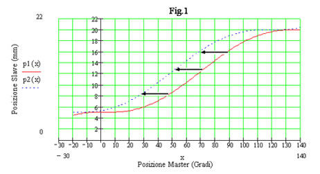
The diagram p1(x) is designed in Fig.1, the profile can be a polinomial of 5° or sin(x), cicloidal and so on.

Note in Fig.1 that the motion of p1(x) (red profile continue) is stopping in position =5mm while the master is in position 0°.
The slave starts with velocity and accelerazion =0 and stops in the position of 20mm while the master is in position 140° following i.e. a polinomial of 5°.
If we shift to left the red profile of 20 degree we obtain the profile p2(x) (blu dot profile) that has the following feature:
p2(x) is p1(x) in advance comparing with master of 20 degree.
That means that the slave starts anticipata nei confronti del master di 20 gradi , questo significa che lo slave partirà dalla stessa posizione y1=5mm quando il master passa per i 340° e termina al valore y2=20mm ma a 120° del master cioè matematicamente significa p2(from the same position y1=5mm when the master crosses in 340° and stop with the value y2=20mm when the master is in 120°.
Mathematically means p2(x) = p1(x+20).
We obtain what is so called a “move phase shift” of the cam profile.
How can we fix the problem mechanically ?
We suppose to have the following mechanic situation with a crank-piston rod and the superior dead point is M=5mm and the inferior dead point is N=5mm.
In that case the shift "O" is the rotaive master and its position is tha angle alfa clockwise.
In that case the axis slave is the position of point "P" and it is a linear axis positive in right direction.
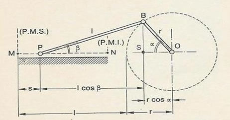
Also, how can I put in advance the cam of 20° comparing with master position?
I have to disconnect the biella from the shift "O" and rotates it of -20°, follows that the motion of the point P in position M=5mm starts when the master "O" is in 340° and not in 0°.
Tat means to stop the machine and changing the mechanic position of some parts.
Electronically can be done with the machine running !!
• CHANGING THE PHASE OF SLAVE COMPARING WITH ITSELF
(MOVE OFFSET)
We have always the same profile.
We shift up the profile of + 4mm.
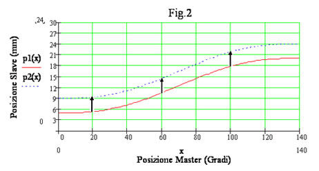
The profile p2(x) is shift up of +4mm comparing with p1(x) ,mathematically
p2(x)=p1(x) + 4.
We obtain a “ Move Offset ” of the cam, also we have shift up all the poits of the final actuator.
How can we fix the problem mechanically ?
We have to modify the lenght of "P" of 4mm to obtain a movement from M=4mm to
N= 24 mm.
Also the electronic cams have the vantage that can be recalculate run-time (mechanically means rebuilding fisically a cam).
More, they have the vantage that can be shift with the machine stopping and/or running.
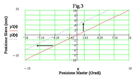
In tha particular case that the relationship between master and slave is a straight the two types of shift are the same.
In other words to do a “Move Phase Shift” in advance is equivalent too do a “Move Offset” to up of Ay=k* Ay where k is the slope of the straight as Fig.3.
We can do analogue considerations about a rotative slave axis like a rotative knife.
The algorithms "FB_MovePhaseShift" , "FB_MoveOffset" is at disposal and written by structured language (IEC1131) and is used wth a function block with "n" inputs and "m" outputs. (see below)
At to day this function block is available in version:
ELAU, Rockwell Automation, Siemens, Indramat, B&R and any other systems that uses language IEC1131.
Please, contact: fabiano.manzan@art-of-motion.it
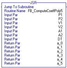
Follows some function blocks to compute somecam profiles:
“FB_ComputeCoeffPoly5”
M“FB_ComputeTabCicloide”

M“FB_ComputeTabCamSraight”
“FB_ComputeTabCamPoly5”
